Hi everyone. I finally got some breathing time. So today during lunch I thought about what would be a great topic to write about. Well I think when dealing with civil engineering, grading design plays a very important part. As we all know, there are many different methods on how to grade. For example, you can do grading with corridors, featurelines. grading groups and points on so on. I have read every books and blogs and I have notices most designers like to use the minimize flat area feature when adding polylines as contours to a surface. After several discussions with our engineers and surveyors, we have learned that the finish product created by C3D in this method does not meet company standards. Though it may look correctly in 2d or on paper, once the survey department begins staking, you will being to get a lot of questions specially along swales. In this post I will show you how I typically do my design grading for areas with large number of swales with polylines.
The image below is the design grading for the subdivision lots, created with polylines (with assigned elevations).
Here I used the typically way most books tell you how to add contours data to a surface. Notice the minimized flat features that was selected.
After the polylines were added, here is what C3D came up with. (See image below) The surface looks correct on paper but is it really correct?
When I looked at the surface in object viewer, I noticed that my swale do not look smooth. Not quiet correct.
In this image, I turned on my tin lines and points in my surface style. Notice all the random points that were added to surface.
For my final test, I did a quick profile across the swales. As you can tell the swale is incorrect. The profiles shows no swale.
After several practice test I found that the only way to correctly do lot grading that meets company standards is by using theses procedures below.
First select all you polyline contours and add by contours. The Add Contour Data dialog will appear. Turn off all the minimize flat area features. See image below. The weeding and supplementing factors is up to you on how tight you want your curve contours to be displayed.
After the surface was built this is what C3D came up with. As you can tell the contours are not quiet correct, specially at the nose of the swales.
In this image I turned on the tin lines and points. One great thing is I don’t have a a bunch of random points in my surface.
After spending some time swapping tin lines at the noses of the swales here is what the finish product should look like at all of your swales. (See image below)
Here is what my swale looks like in object viewer. As you can tell, the swale looks much smoother and is designed correctly.
In the image below I placed a spot grading to compare the two different methods. In the first method, the spot elevation in the swale was 633.96. In my surface design method, the same point grade is 633.37. That’s a big difference to me.
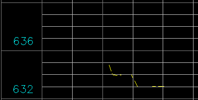
In my final design test, I did a quick profiles at the same location across the swales. The profile clearly shows the swale and the top of the berm.
In conclusion, I personally think this is the best method when grading with polyline contours. Even though it will taking you longer with your design because of the tin swapping that will take place, you will end up with a more accurate surface. On top of that, you will get a more accurate cut/fill calculation when doing subdivision dirt numbers. It could make a difference of 1,000 cubic yards or more depending on the size of the site.. Anyways, I hope you enjoyed the post. Feel free to make comments.