Thursday, May 27, 2010

Roundabout Design Part 1

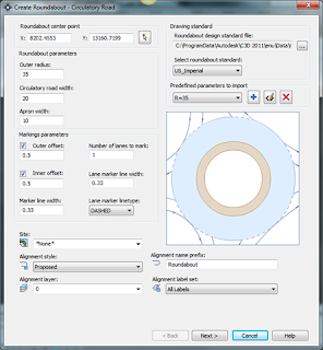
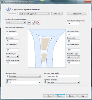
Roundabout and traffic circles are a common form of intersection control used throughout the world and are becoming more and more popular in the United Stated. Civil 3D 2010 was the first to introduce the roundabout feature as a subscription download. The new Civil 3D 2011 has added the roundabout feature to the Home contextual tab under the create design ribbon. The new roundabout feature allows you to create and edit a 2D roundabouts design. The 2D roundabout feature commands can produce roundabout central areas, approach roads, slip lanes, and pavement marking and signage. When you create a roundabout, it automatically created a group of new alignments and polylines that represent roundabout components. Two important items to look for when designing your roundabout is approach lane curb return overlaps and editing the roundabouts.  Roundabouts created using the Create Roundabout command can only be edited in versions of AutoCAD Civil 3D that contain the roundabout creation functionality. I have provided images and A short video presentation on how to create a basic roundabout.
Corridoring a roundabout can be a little confusing and tricky. I just recently designed and corridored two roundabouts in a subdivision I was working on. To save time, I corridored the roundabout with a few profiles and feature lines. You can use the intersection feature but you could be looking at very complex corridor and subassemblies. In part 2 of my post on roundabout, I will show you a few shortcuts on corridoring a roundabout. Please feel free to make comments or email me if you have question.

ROUNDABOUT ARTICLE

CE NEWS


Roundabout Design Part 1

Roundabout and traffic circles are a common form of intersection control used throughout the world and are becoming more and more popular in the United Stated. Civil 3D 2010 was the first to introduce the roundabout feature as a subscription download. The new Civil 3D 2011 has added the roundabout feature to the Home contextual tab under the create design ribbon. The new roundabout feature allows you to create and edit a 2D roundabouts design. The 2D roundabout feature commands can produce roundabout central areas, approach roads, slip lanes, and pavement marking and signage. When you create a roundabout, it automatically created a group of new alignments and polylines that represent roundabout components. Two important items to look for when designing your roundabout is approach lane curb return overlaps and editing the roundabouts.  Roundabouts created using the Create Roundabout command can only be edited in versions of AutoCAD Civil 3D that contain the roundabout creation functionality. I have provided images and A short video presentation on how to create a basic roundabout.
Corridoring a roundabout can be a little confusing and tricky. I just recently designed and corridored two roundabouts in a subdivision I was working on. To save time, I corridored the roundabout with a few profiles and feature lines. You can use the intersection feature but you could be looking at very complex corridor and subassemblies. In part 2 of my post on roundabout, I will show you how a few shortcuts on corridoring a roundabout. Please feel free to make comments or email me if you have question.
ROUNDABOUT ARTICLE
CE NEWS

roundabout_5-27-2010 
image 
image
image image

Tuesday, May 25, 2010

MAY’S CIVIL 3D KNOWLEDGE BASE

i have provide a list of Autodesk answers to a few issues some of us are facing such as blue screens with Nvidia graphic video cards, splash screen closing and targeting specific surfaces.

KNOWLEDGE BASE

Sunday, May 23, 2010

CE NEWS SURVEY

I was reading my CE News magazine for March and I came upon a very interesting article. Here is what the article states “ Shortly after President Obama signed the American Recovery and Reinvestment Act (ARRA) in February 2009, CE NEWS surveyed it’s readers to gauge their attitudes on the prospects for the AEC industry in general and for their firms in particular.” I have provided some of the questions CE NEWS asked and what their readers responses were. I would like to hear your thoughts and response to these questions and how the economy has effected your firm.

CE NEWS MARCH 2010

1. Do you anticipate that the AEC industry will grow, shrink, or remain the same in the next year?

2.  How do you anticipate your firm’s total revenue for engineering services in the next year will compare with the prior year?

3. What is the greatest challenge your firm faces in the coming year?

4. Have you experienced any of the following at your firm during the last 6 months?

ce_news

Thursday, May 6, 2010

C3D 2011 CROP SURFACE

The crop surface feature will come in handy when you have a small project site and you are using USGS contours or aerial contour that covers hundreds of acres. The crop surface feature will allow you to cut area of surface that you need for your project without affect the original surface or source surface. I’m sure some of you are asking why not use boundary and data reference the surface out. Well to answer that question, as far as I know you can not make revision or changes to the data reference surface once you insert it into your drawing. With the crop surface feature you will be able to add points, breaklines, contours…etc. Anyways, this feature would have definitely helped me in my subdivision design I was working on which had 500 acre surface. I have provided a short video below  on how to use the crop surface feature. Remember if you make changes to the original surface and want those changes to reflect to the copied surface, simply select rebuild snapshot then rebuild surface on the copied surface.

.

Tuesday, May 4, 2010

C3D 2011 Other New Features Pt 2

Tonight I played around a little more with C3D 2011 and discovered more new features that I want to share with you.

  1. Crop Surface has been added into the Surface ribbon. This feature allows you to crop an area of surface and export into another drawing or a new drawing. This will come in hand why you have an over USGS surface cover several hundred acres and you only need a small portion of the surface for your site. One rule of thumb, if you make changes to the source drawing be sure to save the current drawing before you rebuild the surface which you just created.

image  image

2. Create Best Fit Profile has been added to the Create Design ribbon under the Home contextual tab. This feature helps  guide you in you design for the best possible and logical path through a series of surfaces profiles and featurelines and other AutoCAD entities.

image   best_fit_profile


3. Application Status Bar has a new look with some new features. First, quick access to your hardware acceleration feature. The 3d orbit, pan, show motion and steering wheel have been removed and added to a floating toolbar on the right side if your screen. A quick to your data shortcut reference has been added. Last but not least, the  Autodesk TrustedDWG link was added which can be used with your TrueView software. 

tool_bar

image


4. Two new features were added to the Ground Data Ribbon. You can now use the minimum distance between surfaces feature. In addition, the resolve crossing breakline feature. This feature will help when you have several breaklines in a EG or PG surface.

image


5. Stage Storage feature has been added to the Design ribbon under the Analyze contextual tab. In 2010 this feature was only available to subscription owners as a download.

image image

Monday, May 3, 2010

CD3 2011 Other New Features

I’m sure a lot of you with subscriptions have download the new Civil 3D 2011 and have started playing with new features. I have provided a list of other smaller new features that have also been added. Make the jump to check out some gems.

Saturday, May 1, 2010

Reverse Storm Profiles

As we all know, when you design storm the alignment always starts downstream because the storm pipes and structures are built from downstream up. Some times you have situation where your storm alignment on plan view  goes from right to left but you profile that's on the same sheet goes from left to right. Some engineers prefer that storm alignment most flow in the same direction. In addition, in some city, they require that your north arrow always point up and right. The best way to handle this to just reverse your profile direction. For those of you that don't know how to set this up, I have provided a short video below.