Friday, March 30, 2012

Civil 3D 2013 New Features Part 2

Good morning to everyone in the AutoCAD universe! Wow this has been an overwhelming exciting week for Autodesk. There has been several webcast this week with the introduction of all the new 2013 Autodesk products. The tweeter world, blogger websites, Facebook, Google+ ,and LinkedIn has been blowing up. So, not only were new features added the 2013 software, the design suite packages received a upgrade . For example, the Autodesk Infrastructure Design Suite 2013 added a few new goodies to the packages. (See image below) The highlighted items are additional software that has been included. I totally love that the Infrastructure Modeler (AIM) 2013 has been added to the Premium package. On top of that, the addition of Revit 2013 and Utility Design 2013 to the Ultimate package makes it a very enticing package to get.

2012-03-28_1508_002[3] 

Anyways, I hope everyone enjoyed the screencast shots that I posted Wednesday from the Blogger Day event. As we all know by now, the three main new features that was added to C3D 2013 was the creation of pressure part network, new survey contextual tab with survey features, and transportation with the incorporation of subassembly composer and Railway Design. Of course there are other hidden gyms that was added but that’s to come later in part 3 and 4. Did everyone notice the new logo? Yes the desktop shortcut icon and application menu icon have changed. (See images below).

2012-03-29_2252 

I have placed the C3D 2013 shortcut icons on top and the C3D 2012 icons at the bottom. So what do you think about the new logo?


2012-03-29_2250  2012-03-29_2249_001 (Application icon for 2012 and 2013


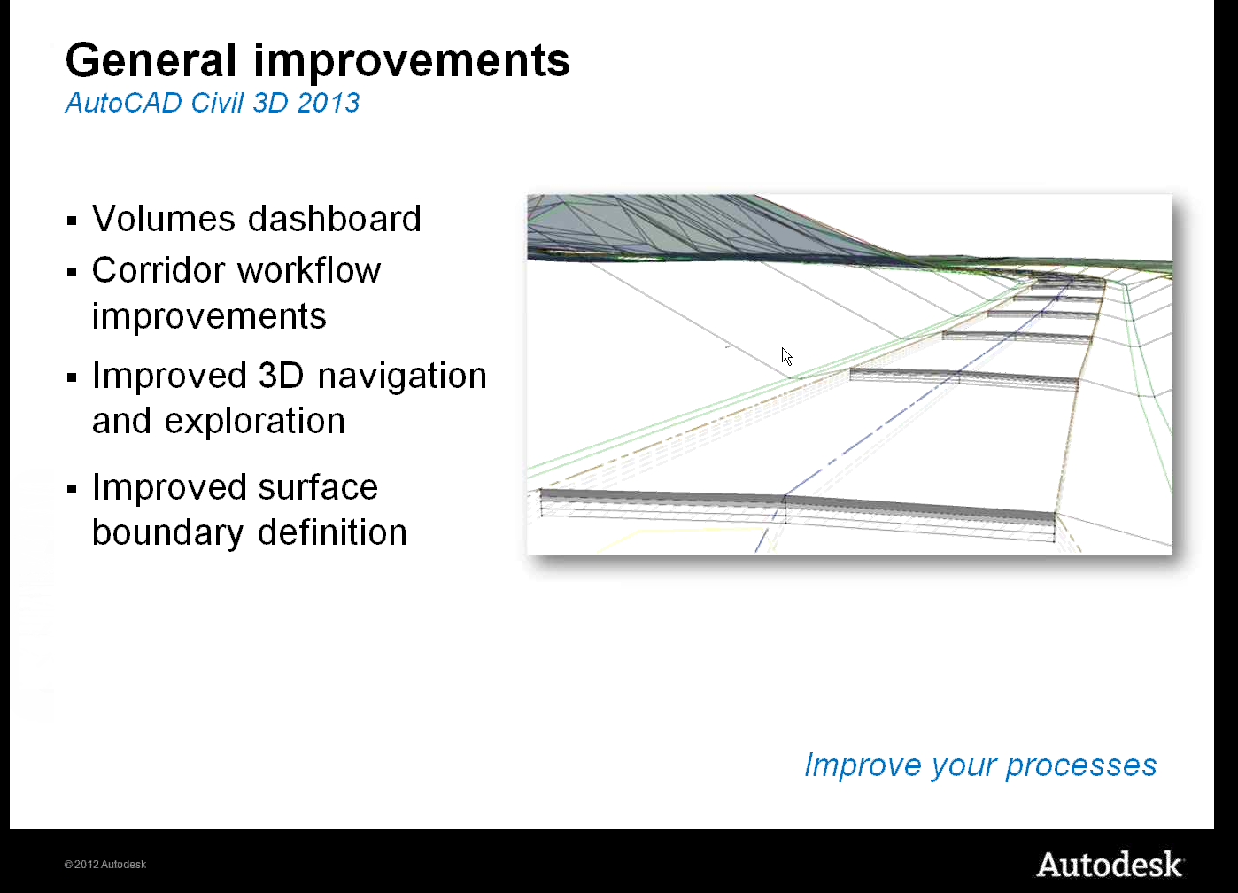
Anyways, today I will skim over the new survey features that was added to C3D 2013. The first thing you will notice and slap you in the face when you open C3D is the new look for the command line. It no longer stretches across the bottom of the screen but has a smaller more slick look. The autocomplete is still present and active. I also want to add the volume dashboard feature can be found in the Analyze contextual tab.

2012-03-30_0005

2012-03-30_0038

2012-03-29_2205

So here is a list of new survey features that you will see on the survey contextual tab/ Survey Modify panel. There are other features that you will also recognize from C3D 2012.

    • Survey Toolspace: Used to open and close the survey tool palette on the C3D toolspace. This tool palette acts as your primary interface when working with survey data
    • Network Properties: Used to change and edit your network name, description and style. Also contains the Edit Network Styles feature.
    • Figure Properties: Used to display survey figures. Also contains the Edit Figure Style to create and edit styles.
    • Survey Query: Used to display the survey query tab. When clicked, the ribbon changes to display the survey query features. (See image below)

2012-03-29_2334

    • Survey Figure Properties : Used to make edits to survey figures
    • Survey Points Properties: Used to make edits to survey points
    • Browse to Survey Data: Used to browse to network, figure and observation.
    • Edit Geometry, Edit Elevation (Used to edit featurelines data and geometry) and ,Update Figure, Update survey data from drawing, and Update Figure from survey data.
    • Mapcheck, Geodetic Calculator, Coordinate Geometry Editor: Also seen in the Analyze contextual tab.
    • Quick Profile, Create Surface and Grading Creation tool: Also seen from the 2012 version.

I think Autodesk is starting to move in the right direction now in improving their survey features and functionality. If Autodesk continues to make improvement on the survey side I can see a larger demand for C3D in the near feature. There is much more in survey improvements but I will get more in depth in part 4. Monday I will do my best to release part 3. Part 3 I will skim over the transportation improvements. I really think some of you will love this topic. Anyways thanks for stopping by and feel free to post comments. Have a great weekend. Smile

Wednesday, March 28, 2012

Hello Civil 3D 2013!!!!!!!

Good afternoon everyone. Today is an exciting day for Autodesk because they officially introduce C3D 2013. Actually this week has been crazy with the announcements of various new 2013 Autodesk products. Yesterday was the introduction of AutoCAD 2013. Anyways, I have posted a several screen shots from the live webcast today. In addition, I have listed a few new features that have been added to C3D 2013. This will be part 1 of 2 post. Tomorrow I will get more in depth with all the new features that was included with Civil 3D 2013.  Enjoy
  • Pressure Pipes modeling
  • new survey contextual tab with new survey features
  • Transportation with improvements in corridor editing and creating assemblies
White Papers: http://usa.autodesk.com/civil-3d/white-papers/
Features: http://usa.autodesk.com/civil-3d/features/


Monday, February 20, 2012

My Thought On Grading With Polylines

Hi everyone. I finally got some breathing time. So today during lunch I thought about what would be a great topic to write about. Well I think when dealing with civil engineering, grading design plays a very important part. As we all know, there are many different methods on how to grade. For example, you can do grading with corridors, featurelines. grading groups and points on so on. I have read every books and blogs and I have notices most designers like to use the minimize flat area feature when adding polylines as contours to a surface. After several discussions with our engineers and surveyors, we have learned that the finish product created by C3D in this method does not meet company standards. Though it may look correctly in 2d or on paper, once the survey department begins staking, you will being to get a lot of questions specially along swales. In this post I will show you how I typically do my design grading for areas with large number of swales with polylines.

The image below is the design grading for the subdivision lots, created with polylines (with assigned elevations).


Here I used the typically way most books tell you how to add contours data to a surface. Notice the minimized flat features that was selected.


After the polylines were added, here is what C3D came up with. (See image below) The surface looks correct on paper but is it really correct?


When I looked at the surface in object viewer, I noticed that my swale do not look smooth. Not quiet correct.


In this image, I turned on my tin lines and points in my surface style. Notice all the random points that were added to surface.


 For my final test, I did a quick profile across the swales. As you can tell the swale is incorrect. The profiles shows no swale.


After several practice test I found that the only way to correctly do lot grading that meets company standards is by using theses procedures below.

First select all you polyline contours and add by contours. The Add Contour Data dialog will appear. Turn off all the minimize flat area features. See image below. The weeding and supplementing factors is up to you on how tight you want your curve contours to be displayed.


After the surface was built this is what C3D came up with. As you can tell the contours are not quiet correct, specially at the nose of the swales.


In this image I turned on the tin lines and points. One great thing is I don’t have a a bunch of random points in my surface.


After spending some time swapping tin lines at the noses of the swales here is what the finish product should look like at all of your swales. (See image below)


Here is what my swale looks like in object viewer. As you can tell, the swale looks much smoother and is designed correctly.


In the image below I placed a spot grading to compare the two different methods. In the first method, the spot elevation in the swale was 633.96. In my surface design method, the same point grade is 633.37. That’s a big difference to me.


In my final design test, I did a quick profiles at the same location across the swales. The profile clearly shows the swale and the top of the berm.


In conclusion, I personally think this is the best method when grading with polyline contours. Even though it will taking you longer with your design because of the tin swapping that will take place, you will end up with a more accurate surface. On top of that, you will get a more accurate cut/fill calculation when doing subdivision dirt numbers. It could make a difference of 1,000 cubic yards or more depending on the size of the site.. Anyways, I hope you enjoyed the post. Feel free to make comments.