Sunday, December 1, 2013

EXPERIENCE AU ONLINE

11-21-2013 1-11-40 PM


Good morning everyone. Now that AU is just 2 days away, I would like to provide some links to those not able to attend AU.  I have listed below several links for several social sites that you can follow covering AU 2013.  The Autodesk University website provides links to watch the opening keynote address and several classes that you watch live throughout the week. In addition, you can also follow AU with LinkedIn, Twitter and Facebook to see comments, videos and pictures being posted. On top of that, you can also follow me on Google+ and Twitter as I post live pictures from classes, roundtable discussions, video interviews, exhibit hall, AUGI Beer Fest, Social Media and much more. I will try to post at the end of each night my experiences of that day on here. Anyways, I am definitely excited about the trip. What surprises does AU have for us this year?? Smile  Stay tune.


Autodesk University 2013 Live

LinkedIn - AU Group

Twitter - AU 2013

Facebook - AU 2013

Tuesday, November 19, 2013

Autodesk Vehicle Tracking 2014

Every project we work on, whether you are an architect or engineer,  we perform some type of design analysis to ensure our design meets local, state, or federal construction standards. In Civil 3D, we can perform slope, grading, sight distance, drainage and hydraulic, road vertical analysis and much more. Now with the new addition of Autodesk Vehicle Tracking 2014 software, we can now add vehicle swept path analysis to the list. 

Just early last week, Autodesk introduced the new Autodesk Vehicle Tracking 2014  (formally known as Auto Track) software to the world. This software was acquired by Autodesk from Savoy Computing Services in August.  Autodesk Vehicle Tracking software performs transportation analysis for vehicle swept path. In addition, it also provides design solution for vehicle movements in areas such as parking lots. The software also allows you to evaluate steering  movements for light rail vehicles and aircrafts. Last but not least, Autodesk Vehicle Tracking can assist in designing parking lots and road intersections such as roundabout. Another positive note about the software is that it is fully integrated into Autodesk software such as AutoCAD, AutoCAD Civil 3D, AutoCAD Plant 3D, AutoCAD Map 3D and AutoCAD Utility Design software. With capabilities of 3D modeling, performing vertical clearance, vertical grades and crossfalls, this software can help designers and civil engineers optimize their design faster.

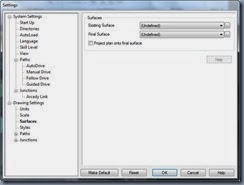
 I have provided several screenshots of the numerous setting and features that comes with this software. Enjoy
 

11-16-2013 10-37-48 PM

The Vehicle Tracking Ribbon

11-16-2013 10-41-14 PM

Settings

11-16-2013 10-42-04 PM 11-16-2013 10-43-24 PM

11-16-2013 10-49-48 PM 11-16-2013 10-50-37 PM

11-16-2013 10-51-46 PM  11-16-2013 10-52-38 PM

Vehicle Library

11-16-2013 10-53-32 PM 11-16-2013 10-54-20 PM

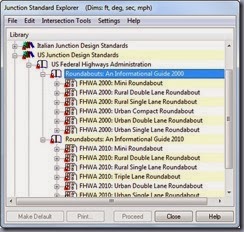
Roundabout standards and Vehicle Positioning

11-16-2013 11-00-45 PM 11-16-2013 11-25-15 PM

Video: Autodesk Vehicle Tracking

Though Autodesk Vehicle Tracking is a powerful software with numerous tools it does has it’s bugs like most software, but don’t let this deter you from downloading it and taking it for a spin. See links below for known issues and documents. Thanks for stopping by and feel free to make comments. Have a great week and hopefully I will see a few of you at AU.

KNOWN ISSUES

DOCUMENTS

Monday, November 4, 2013

Creating Shapefiles from Civil 3D Parcels

Good evening everyone. In this post I would like to share a tip on how to create shapefiles from Civil 3D parcels. So far this is the only way I know how to convert parcels to shapefiles but I am sure there are other methods out there. Hopefully this will be helpful to some of you.

Before we get started we have to discuss coordinate system. We all know all firms are different and have different workflows. Some firms may create their plats in state plane and some on surface. If your plat containing your parcels was created on surface, you will have to perform a coordinate conversion or move the data once it has been import from an SDF file. In this example I will make my drawing in state plane to simplify things.

  • Open the drawing that contain the parcel data you wish to transfer.
  • Select the OUTPUT Tab on the ribbon then select Export Civil Objects to SDF.

11-4-2013 6-25-07 PM

  • The Export to SDF dialog box will appear. On the first row, browse to the desire location you wish to save the SDF file and assign a name. Then set the coordinate system if not assigned.

11-4-2013 6-20-52 PM

  • Next, open a new drawing and set the same coordinate system as the file we just saved.
  • On the command line type MAPIMPORT and browse to the SDF at we just created and select OK.
  • The import dialog box will appear. Check the Import polygon as close Polylines options. Then under the DATA column click the small selection box.

11-4-2013 6-40-02 PM

  • The Attribute Data dialog box will appear. As the default the Do not import attribute data will be selected. Select the Create Object Data. Then click on the Select Fields button.

11-4-2013 6-41-20 PM

  • The Object Data Mapping dialog box will appear. For now I will select all the targeted fields and select OK twice.

11-4-2013 6-44-52 PM

  • This will take you back to the Import dialog box. You will now see a data file under the Data column. Click OK.  All the closed parcels areas should appear in your drawing as closed polylines now. At this stage, if you drawing was not on state plane but on surface you can now move all the linework to the correct location before we export to a shapefile.

11-4-2013 6-52-25 PM

  • On the command line type MAPEXPORT. The Export Location dialog box will appear. Select a folder or create a folder that you wish to save all your GIS data for your shapefile and assign a file name. Then at the bottom under Files of Type select ESRI Shapfile (*shp.)

11-4-2013 7-17-47 PM

  • The Export dialog box will now appear. For the option type select Line. Under the Select Objects to Export click Select All. You can also assign a layer for all your objects.

11-4-2013 6-54-44 PM

  • Now select the DATA tab. As a default there are no attributes. Click the Select Attributes button.
  • The Select Attributes dialog box will appear. Expand Object Data and check the Parcels options. (It may appear as the SDF file that we created) For now I will select to export everything. Click OK

11-4-2013 7-06-37 PM

  • This will take you back to the Export dialog box. You will now see attributes in the source Fields column. Click OK

11-4-2013 7-11-47 PM

  • After a few seconds all the polylines in your drawing will be converted to shapefiles. If you look under the project folder that you assigned to save all your GIS data you will see several new files such as idx, cpg, dbf, prj, shx, and your shapefile. You will need to send all these files with your shapefile.
  • Before you send your new shapfile out the door, I would run a quick test by import the shapefile using the Data Connect feature in the Planning & Analysis workspace or the MAPIMPORT command and import the new shapefile. Then use the GEOMAP feature to ensure all the linework aligns with the aerial and appears in the correct location. Anyways I hope this information will be useful to you. Have a great week and thanks for stopping by.

Wednesday, August 21, 2013

Imaginit Google Earth Import in Civil 3D 2014

Good morning everyone. This morning I would like to share some interesting and maybe important information to a few of you. As we all know, the Google Earth extension in C3D 2012 was a power tool that most of us utilize on a daily or weekly basis. That feature was removed and replaced in the 2013 version with the Project BaseJump (Bing Map extension). The Bing Map extension was useful but there was a few draw backs with printing and saving images. Well, just recently our reseller Imaginit released a new 2014 Utility application tool that put a smile back on my face and our planners. Imaginit Utilities for Civil 3D 2014  includes the AutoOffset, Point Station Report, and last by not least, Import from Google Earth. This feature allows you to bring in aerial images (georeferenced images) and terrain tin surface or both straight into Civil 3D.

Imaginit is our reseller and subscription account holder for all of our Autodesk software. For those who have subscription thru Imaginit, the Utilities for Civil 3D 2014 is free. In addition, you can download the stand-alone or named-user versions. With the stand-alone installation, you are only allowed 10 seats. You may want to contact Imaginit if you need more. If you are interested in purchasing or finding more information about the Utilities for Civil 3D 2014 or other software click link below.

Imaginit Civil Engineering

The download and installation is quick and easy. After you have completed the installation, you will see a new Imaginit tab on the ribbon. I have provided below a short video presentation on how easy it is to import Google Earth images now. I also like to add, that you can insert as many images as you like. In order for this feature to work your drawing must have a coordinate system assign such state plane. Currently all the images are saved locally on your C drive but you can easily move and relink the images in your xref manager. I have not tested the other utility tools yet but you can contact Imaginit to get a free demo to test. Hopefully this information will be useful to a few of you. Thanks for stopping by.

8-21-2013 7-19-44 AM

8-20-2013 8-01-31 AM

Imaginit Google Earth Import

Wednesday, August 14, 2013

Autodesk Software Training Companies

Hi everyone. I hope everyone is enjoying their week. Our company just recently had our yearly company campout. I was able to take my daughter for the first time and she had an amazing time swimming and tubing at the lake. Our company campout is a whole weekend event where everyone kicks back relaxes, have a few drinks, grill, swim, listen to music,  tube, fish and play some golf. We work hard but we also play hard. Overall, it’s a great experience for all of our employees and family.

Anyways, tonight I want to share some great training companies that provide different verity of training resources such as live online classes, classrooms, recorded webcasts, courseware and customize training. I have listed below (in no particular order) a few training companies that I know of. As we all know, training is crucial for all cad users. I always tell our techs and engineers that our design software is only as good as the user. Providing  training in-house or by an out source company is vital for all engineering firms. I always encourage our techs and engineers to watch training videos, read one a few pages from one of our many Civil 3D books, or even just practice playing around with features on the ribbon during their free time. Anyways, hopefully this information will be useful to a few of you. Thanks for stopping by and enjoy.

Friday, June 14, 2013

The New Certified BIM Specialist: Road and Highway Solutions 2014

Good morning everyone. I hope everyone is having a great week. It has been a crazy two weeks for me dealing with implementation and customization of our 2 new telephone & internet services at our two offices. On top of that, helping with the setup and installation of several new workstations and coordination with the IT Dept. with the planning and implementation of our new network server this week. In addition, kicking  off two new large projects. Fun!

Anyways, I just found out some very interesting news from Autodesk today. It seems Autodesk has just created its first BIM certification exam: Certified BIM Specialist: Road and Highway Solutions 2014. This certification exam will test the knowledge and skills of designers, engineers and land planners using the BIM workflow across multiple software platforms using the Infrastructure Design Suite to creating and modifying road and highway designs. The exam topics covers over Project planning, Preliminary design, Detail design and  Visual communication. If you would like to learn more about this certification exam see links below.

Personally, I think this is a great step for Autodesk. I was wondering how long it would be before something like this would start. Even though this test mostly uses InfraWorks and Civil 3D, I hope to see another exam that will incorporate Naviswork and 3ds Max Design. So what will that certified specialist be called then? Jedi? lol. Anyways, thanks for stopping by and feel free to make comments.


Podcast Interview With Cathy Palmer

Autodesk Certification Handout

Ascent 2014 Certification Training Courseware List

Friday, June 7, 2013

Civil 3D 2014 Round-Tripping With Corridors

Hi everyone. I don’t know if everyone has noticed, but the economy is booming. Working 12 hours shifts is starting to be a norm for me now. That’s why I have not been posting much lately. Sorry. Anyways, I have noticed a lot of post on Google+, tweets and Autodesk forums about round-tripping with corridors not working and causing fatal errors and crashing. So I decided to do my own test and post my results here. Sorry the video has no audio.

  1. In this first video, I opened a subdivision grading design base drawing containing all of our proposed features lines, grading groups, surfaces, alignments and profiles. This drawing was originally created in 2013 and upgraded to 2014. I ran some simple tests and it ran smoothly. See video.


Corridor Round Tripping Test 1


2. In this next video I created a very simple corridor in 2014. I then opened the same drawing in 2013 and ran a few quick test. Even though it was not a large corridor drawing I feel confident that I would get the same results. The most interesting thing about these results were that when I tried these same test at my home computer it crashed and fatal error. The only difference between my home and work workstation is network connection and memory. My work computer has 24 GB memory and my home PC has 8 GB. I then tried the same test with a another workstation at work that only had 8 GB  of memory with a slightly older processor and had no issue or errors. Anyways, I know everyone has different templates and workflows but email me if you have a drawing that keeps crash in 2013 and I will run a test with my workstation and see if it crashes on me. Feel free to make comments. Thanks for stopping by.


Corridor Round Tripping Test 2